In the beginning of 2018, I've discovered a Kickstarter project, called "The Little Buddy Talker". It's a small chip on a breakout board with 254 short voice messages and a 3.5mm audio jack.
Connection
The Little Buddy Talker is connected via SPI to the Arduino. And since TLBT is mounted on a breakoutboard with pins on the bottom, you can easily put it on a breadboard for wiring.
The Sound Chip
The chip on the board is the aP23682. It's a voice IC with the capability of recording up to 682sec voice in a 16bit quality. With this chip, you could probably make your own buddy talker. All you need are the voice samples.
Video
What could have been better?
Since the buddy talker is connected via SPI, it would be usefull, if it had the standard SPI connector matching to the one on the Arduino Uno, Mega or Nano.
The buddy talker doesn't give any feedback, that indicates when a sound file has finished.
Well, I needed an eye catcher for the Maker Faire Ruhr 2018. Moving lights always gain the interest of people. Which includes me as well. The idea behind it: a LED stripe that changes color in response how close you get to it. The distance can be easily determined by a ultrasonic sensor. And with a Neopixel stripe I could easily change the color. But wait! With the Neopixels I can control each pixel individually. So instead of using one ultrasonic sensor, I'm using five. Each of the sensors triggers a different piece of the LED stripe.
Problem
If you want to measure the time the sound takes to travel towards an object and back, you would usually use the puleIn-function. The problem is, that while the micro controller measures the time it does nothing else. So you would have to wait for the signal to return, before you can trigger another ultrasonic sensor. But we want to be able to operate several sensors simultaneously. I was about to imagine a proper algorithm, when I found out, that I wasn't the first to encounter this problem. And I'm not the first to find a solution for it. The library handles this issue.
The Build
I've found a wooden plank from a slatted frame with a length of 135cm. Perfect! I'm using one meter in the middle for placing the Neopixel stripe and five ultrasonic sensors.
The diameter of the ultrasonic sender and receiver tubes are close to 16mm. This is a drill size I had to purchase. I predrilled the holes with a 3mm drill, before using the 16mm one.
First I tried to glue the Neopixel stripe on to it, but that wouldn't hold. I fixed them with zip-ties.
I used an Arduino Nano as the controller, soldered a custom PCB and glued it on the back side of the lath.
I wanted the build to be robust. So I soldered wires from every sensor to the PCB. So that nothing will accidentally disconnect though the transport.
The Algorithm
The original design was that all LEDs were lit white when the maximum distance of three meters is detected. Technical speaking the values of all three colors are set to 254. The value of green and blue is now determined though the distance of an object to the sensors. Well it looked quite unspectacular, but it worked.
Video
Wiring
The power from the Arduino will not be enough to power all sensors and the LED stripe. So you need to add an external power line (5V).
While I'm making videos for you, it is often necessary to write something important down. Sometimes just, so remember the identifier of the item. Or do you really think I can remember things like "ADXL345" or "VL53L0X"? And honestly: I haven't got much paper in my flat. So I thought about getting a some kind chalkboard. Less waste than writing on paper.
The e-Writing Board
I came across this little gadget. It's like a tablet where you can write on it with a stylus or your finger. I must have this thing! I asked Banggood, if they can provide me with one of those boards and they agreed.
That e-writing board is such a lightweight, I'm afraid to break it. And have you ever had a Etch-A-Sketch in your childhood? You could "write" and draw on a board without any batteries.
Different sizes
This board seems to be available from 4.5" up to 12" from different manufactures. And they are awesomely cheap! Haven't found one that exceeded the 25 € mark.
Video
Summary
Pro
- Cheap
- Lightweight
- Low power consumption (Battery used only for erasing)
- Lock screen switch prevents accidental deleting
Many devices uses current on standby mode. So we like to plug them into a power stripes with a switch on it. And we hide it behind some furniture because it's quite ugly to look at some cables. But now it's hard to reach. So.. if we could control the switch remotely within the comport of our couch? That's what IoT is made for.
Wiring
Video
Attention!
Working with 110V AC or 230V AC is very dangerous and should be done only by a professional! Not only can it kill you, you also suffer incredible pain while you die!
Configure MQTT-Client
The MQTT broker and your client device has to be either in the same network or at least reachable through the internet (not really recommended).
You enter the IP and port of your broker to connect to it.
Add a new widget for on/off mode.
Then you subscribe to the channel the ESP is sending it's status to. It is: "esp/3/power/out" in this code.
You need now to enter the channel, where you want to publish commands to. The ESP subscribes messages from this channel. I used "esp/3/power/in" for this case.
Now, the only thing left to do is to define the messages for on and off. Usually it would be best to use 1 for on and 0 for off. I go for 10 for off and 11 for on.
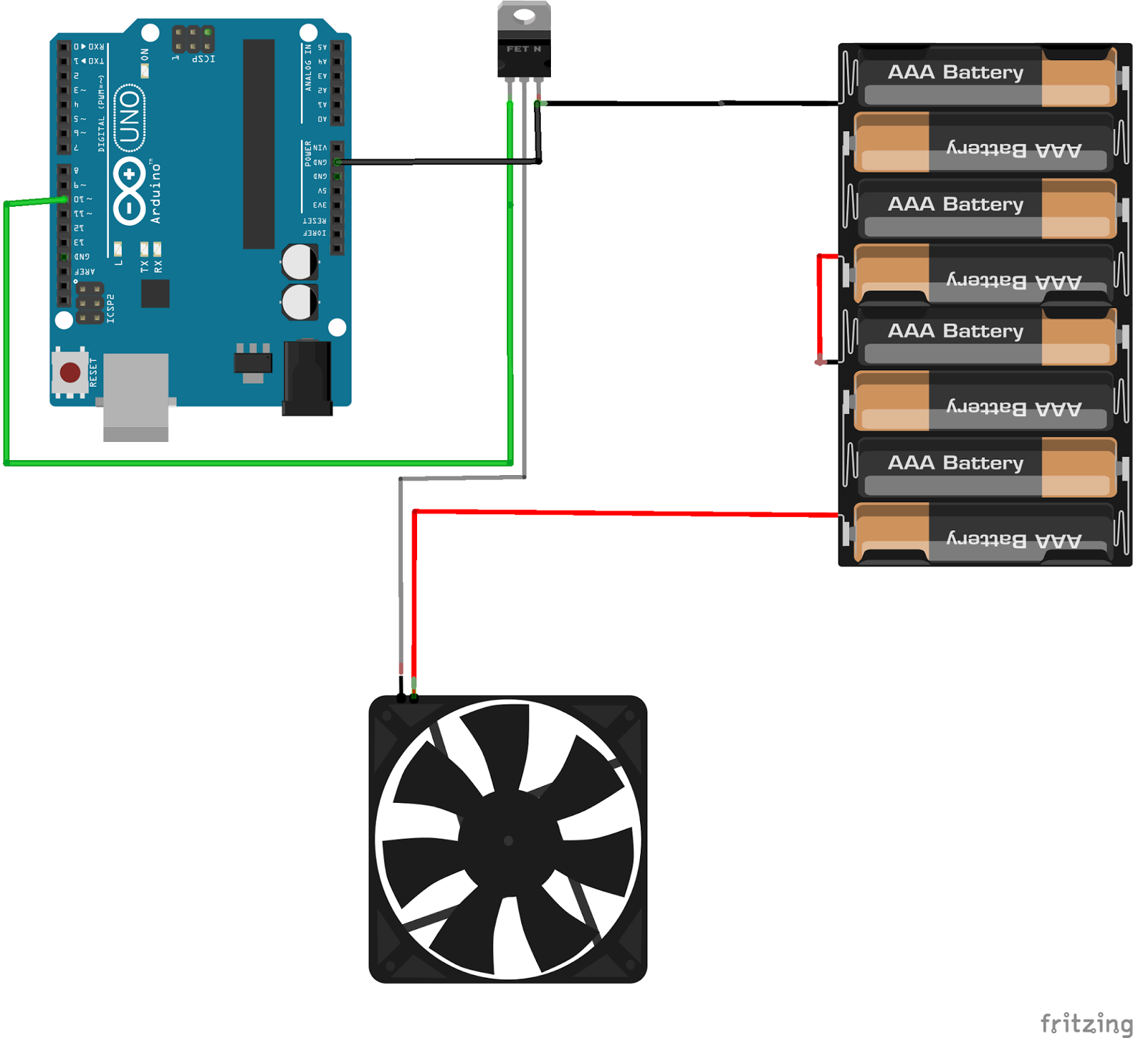
You savaged a fan from an old PC to use it as a ventilator? Just hook it up to 12V and the sucker runs. Well, it runs at a constant speed. Maybe too fast, maybe too noisy. There must be a possibility to slow it down.
The idea
When you apply 12 Volts to it and then remove the power supply, it keeps spinning while getting slower. So if you continuously apply and remove the power, you can control the fan of the speed by the duration of the phases when the 12V is on and when it is not.
What do we need
The Arduino doesn't supply 12 Volts. So we have to use some sort of switch. An electronic switch. A MOSFET. That's a kind of transistor, that can handle the needed current/voltage needed. I used the IRF530N, because it was the only Mosfet I had and it matches the specification of the vent by far ;-). It's a N-channel Mosfet. That means you can control the connectivity of the negative pole of the power source to the fan by applying a positive voltage.
PWM
Pulse Width Modulation is the magic phrase. A digital output pin can only have two possible states. On or off. 1 or 0. HIGH or LOW. While HIGH is typically indicated by an output of 5 Volts (3.3 Volts occasionally) is LOW represented by a 0 Volt output. So how do we simulate an output of 2.5 Volts? Well, simply spoken, if we have a time frame of 10 seconds. Half the time we put out 5 Volts and half the time 0 Volts, we will have an output of 2.5 Volts of the time of those 10 seconds. Wired? Sure. But this is how math works ;-)
Controlling a servo just by the wave of your hand? The wet dream of every Star Wars fan, isn't it? Yeah, mine too! With Microsoft's Kinect or OpenCV and a webcam and a ton of programming you can do it! Or there is a tiny, little module for your Arduino or your Raspberry Pi that can handle some simple gestures. The APDS-9960 can do the job.
It can be set to three different modes. It can work as a proximity sensor. Well, of that we have quite enough in the Arduino world. It can also operate as a ambilight sensor. Not bad. With four of them - each for every corner of your TV - you can make your own low cost ambilight.
But the mode, we're looking for, is the gesture recognition mode. It can detect following hand-movements: - left to right - right to left - up to down - down to up - close to far - far to close
How to use
Well, this is a multi functional sensor. It is developed by SparkFun. Therefore SparkFun published a pretty good library with very useful examples. If you pick the GestureTest example, you can implement easily your own control mechanism.
Video
Connections
Careful
There are some versions of the sensor, marked as APDS-9960, that are really a APDS-9930. That means they are lacking the coolest of all functions - the gesture recognition thing!
Turning a DC motor on and off isn't that much of a problem, is it? But if you want to change direction, you must have a way to switch the polarity that drives your motor. Well, that is what a H-bridge does.
How to control
For each motor, you should have 2 pins to control the output. If you pull one pin HIGH and the other one LOW the motor should spin. If you invert this configuration, the motor will spin in the other direction. Pulling both pins to LOW or both to HIGH will stop the motor.
Now you have the ability to turn the motor on in both directions. If you also want to control the speed of the motors, you should connect it to PWM ports.
Wiring
Video
Pro-Tip
If your motor doesn't spin, you probably have a too low input voltage. These boards are equipped with voltage regulators. So you can try using a higher voltage. I used a 9V battery for the 5V motors myself. Worked perfectly.
For controlling your robot it makes sense to extract the commands for the wheel to spin in separate methods. Make a method for spinning the left wheel in clockwise direction. And one for counterclockwise direction. It's so easier to program some logic to your vehicle.