Friday, November 10, 2017

IoT - power it up!


Intro

Many devices uses current on standby mode. So we like to plug them into a power stripes with a switch on it. And we hide it behind some furniture because it's quite ugly to look at some cables. But now it's hard to reach. So.. if we could control the switch remotely within the comport of our couch? That's what IoT is made for.

Wiring


Video


Attention!


Working with 110V AC or 230V AC is very dangerous and should be done only by a professional! Not only can it kill you, you also suffer incredible pain while you die!

Configure MQTT-Client

The MQTT broker and your client device has to be either in the same network or at least reachable through the internet (not really recommended).
You enter the IP and port of your broker to connect to it.
Add a new widget for on/off mode.
Then you subscribe to the channel the ESP is sending it's status to. It is: "esp/3/power/out" in this code.
You need now to enter the channel, where you want to publish commands to. The ESP subscribes messages from this channel. I used "esp/3/power/in" for this case.
Now, the only thing left to do is to define the messages for on and off. Usually it would be best to use 1 for on and 0 for off. I go for 10 for off and 11 for on.

Links

ESP 8266 NodeMcu @ Amazon
Relay @ Amazon
Simple Power strip @ Amazon
Finding a Smartphone @ Amazon

Update

Code for the ESP 8266
https://bitbucket.org/Remnis/mqtt-iot-switch

 
 Banggood 11.11 Global Shopping Carnival Electronic Special -- https://goo.gl/zHEiJW

Thursday, October 12, 2017

Controlling the fan speed with your Arduino


Intro

You savaged a fan from an old PC to use it as a ventilator? Just hook it up to 12V and the sucker runs. Well, it runs at a constant speed. Maybe too fast, maybe too noisy. There must be a possibility to slow it down.

The idea

When you apply 12 Volts to it and then remove the power supply, it keeps spinning while getting slower. So if you continuously apply and remove the power, you can control the fan of the speed by the duration of the phases when the 12V is on and when it is not.

What do we need

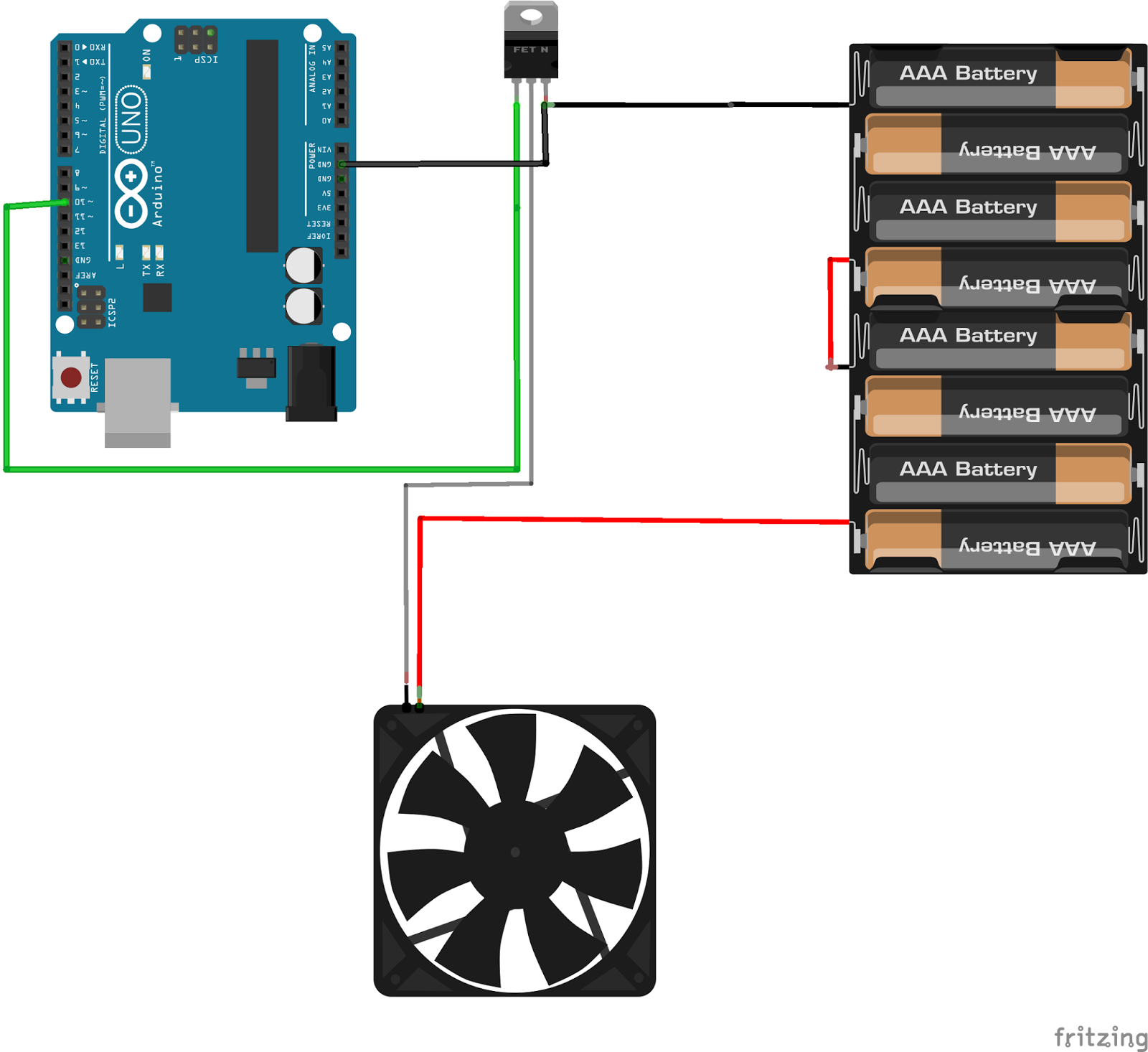
The Arduino doesn't supply 12 Volts. So we have to use some sort of switch. An electronic switch. A MOSFET. That's a kind of transistor, that can handle the needed current/voltage needed. I used the IRF530N, because it was the only Mosfet I had and it matches the specification of the vent by far ;-). It's a N-channel Mosfet. That means you can control the connectivity of the negative pole of the power source to the fan by applying a positive voltage.

PWM

Pulse Width Modulation is the magic phrase. A digital output pin can only have two possible states. On or off. 1 or 0. HIGH or LOW. While HIGH is typically indicated by an output of 5 Volts (3.3 Volts occasionally) is LOW represented by a 0 Volt output. So how do we simulate an output of 2.5 Volts? Well, simply spoken, if we have a time frame of 10 seconds. Half the time we put out 5 Volts and half the time 0 Volts, we will have an output of 2.5 Volts of the time of those 10 seconds. Wired? Sure. But this is how math works ;-)
PWM


Video


Wiring


Links
IRF530N at Amazon

PWM-Image
https://commons.wikimedia.org/wiki/User:MatthiasDD


Monday, October 9, 2017

Use the force, Maker!


Into

Controlling a servo just by the wave of your hand? The wet dream of every Star Wars fan, isn't it? Yeah, mine too! With Microsoft's Kinect or OpenCV and a webcam and a ton of programming you can do it! Or there is a tiny, little module for your Arduino or your Raspberry Pi that can handle some simple gestures. The APDS-9960 can do the job.
It can be set to three different modes. It can work as a proximity sensor. Well, of that we have quite enough in the Arduino world. It can also operate as a ambilight sensor. Not bad. With four of them - each for every corner of your TV - you can make your own low cost ambilight.
But the mode, we're looking for, is the gesture recognition mode. It can detect following hand-movements:
- left to right
- right to left
- up to down
- down to up
- close to far
- far to close

How to use

Well, this is a multi functional sensor. It is developed by SparkFun. Therefore SparkFun published a pretty good library with very useful examples. If you pick the GestureTest example, you can implement easily your own control mechanism.

Video

 Connections 

 Careful

There are some versions of the sensor, marked as APDS-9960, that are really a APDS-9930. That means they are lacking the coolest of all functions - the gesture recognition thing!

Links

SparkFun Library @ Github
APDS-9960 @ Amazon

Wednesday, August 16, 2017

H-Bridge for your robot


Intro

Turning a DC motor on and off isn't that much of a problem, is it? But if you want to change direction, you must have a way to switch the polarity that drives your motor. Well, that is what a H-bridge does.

How to control

For each motor, you should have 2 pins to control the output. If you pull one pin HIGH and the other one LOW the motor should spin. If you invert this configuration, the motor will spin in the other direction. Pulling both pins to LOW or both to HIGH will stop the motor.
Now you have the ability to turn the motor on in both directions. If you also want to control the speed of the motors, you should connect it to PWM ports.


Wiring


Video 


Pro-Tip

If your motor doesn't spin, you probably have a too low input voltage. These boards are equipped with voltage regulators. So you can try using a higher voltage. I used a 9V battery for the 5V motors myself. Worked perfectly.

For controlling your robot it makes sense to extract the commands for the wheel to spin in separate methods. Make a method for spinning the left wheel in clockwise direction. And one for counterclockwise direction. It's so easier to program some logic to your vehicle.

Buy at Amazon

H-Bridge L298N
5V DC Motor with gearbox
Robot chassis with motors
H-Bridge L9110

Monday, July 24, 2017

Text on your Display


Intro

If you want to add some visual output to your Arduino projects, you'll need a display. If you need only little to display, the LCD 1602 is a quite good solution. But you'll waste about 8 Pins on your Arduino for the display to get working. Luckily there exists a I2C adapter that you can solder right onto the pins of the display. So all you need to connect are the I2C pins, a good library and little of coding.

Wiring 

If you already have the I2C adapter soldered onto the board, wiring is quite easy. You should usually have only four pins to hook up. VCC and GND of course. The LCD display works with 5 Volts. So we go for the 5V Pin. The Arduino Uno and Nano can handle the current need for this display. SDA (data line) to analog 4 on your Arduino Uno or Nano. And SCL (clock line) to analog 5 (other Arduinos or ESP might have different pins).


Video


Needed library

https://github.com/fdebrabander/Arduino-LiquidCrystal-I2C-library

When thinks aren't working

  • Did you remember to call the begin()-method of the library?
  • Did you turn the backlight on?
  • Have you tried to adjust the contrast with the potentiometer on I2C adapter?
  • Did you check the I2C address? (use the i2cdetect sketch)

Where to buy

You can search on eBay for LCD1602 I2C. You'll get plenty of results.
Or, here are some direct links to Amazon:

LCD 1602 with I2C adapter

LCD 1602 without I2C adapter

I2C adapter

The bigger LCD 2004

Monday, June 12, 2017

Extend your analog inputs


Intro

Is yours too small? You want to get more? No, that is no advertisement for a penis enlargement product. It's for a board to extend the numbers of analog inputs to your microcontroller.
It's quite rare that you run out of analog inputs, when using an Arduino Uno, Nano, Micro, etc. Even a ATTiny is already equipped with 4 analog inputs. BUT if you are so keen in using a ESP8266, like I am, you'll find your self in the position having only 1 (!)  analog in. This is where a digital to analog converter comes into play.


It's all about libraries

The name of the sensor (ADS1115) already can lead to the conclusion that the board is developed by Adafruit. And of course, if you'll open the library manager in the Arduino IDE and search for ADS1X15. There you have it all. Ready-To-Use library, good commented examples.

I2C on your NodeMcu board

The default pins for I2C on the NodeMcu board are pins D1 (SCL) and D2 (SDA). But the cool thing with the NodeMcu board is, you can define for yourself where the I2C has to be.

With the command:
Wire.begin();
You usually start the Wire-library, that is responsible for the I2C bus. But you can also add the pins for SDA and SCL as parameters:
Wire.begin(D2, D1); // Wire.begin([SDA-Pin],[SCL-Pin]);

There can be more than one

The ADC1115 has a fixed I2C address, like any other I2C device. Fixed? Not quite! It has up to five different I2C addresses. The default one, and four more addresses, that you can select by connecting the address pin (ADDR) with either SDA, SCL, GND or VDD.


Video


Wire up

Normal wiring


Wiring with two modules on I2C


Links

Adafruit Library
https://github.com/adafruit/Adafruit_ADS1X15

Amazon
ADS1115
NodeMcu

Friday, June 2, 2017

Keeping balance with a gyroscope


Intro

"I like to move it, move it! I like to move it, move it!"
If you want to measure movement, you probably will use one of these sensors. Why you want to measure movement anyway, you ask? Hey, who doesn't want to build a quadcopter? Or a self-balancing robot?
 There are 2 common senors, that will do the trick. The GY-61 (ADXL335) and the bigger brother the GY-291 (ADXL345).

The sensors

The GY-61 is the easier sensor to handle. It has VCC and GND and three analog outputs. One for each axis. You can read the sensor values with the analog inputs of an Arduino.
These are quite raw values. And even, when the sensor doesn't seem to move, the values does. So you have to program some method to smooth these values and probably a calibration routine, if you want to use it in a matter of a balanced project.
The GY-291 is a little different. It has an I2C bus. And I recommend to use the library, that is provided by Adafruit. If you're using the Arduino IDE, just search for ADXL345 in the Library Manager.


Video


Which sensor for which project?

Well the advantage of the GY-291 is, that you don't need to interpret the sensor values for yourself. The library does all the work for you. And it has a I2C bus. That means, you won't waste any pins on your controller. Because you can attach several devices to I2C, as long as they have different addresses. The smaller brother, the GY-61, doesn't need much code to operate. The sensor delivers it's values through 3 analog outputs. Well, at least it delivers something. You have to interpret the values for yourself. If you want to build something like a self balancing robot, I would recommend, that you build a small calibration routine. 
Both sensors costs about the same. 
For one of my next projects, where I want to use an ATtiny. Since the ram of this board is extremely limited and I just want to know, if the sensor is moving anyhow, I'll stick to the GY-61.

Links

Amazon