The 4x4 Keypad is technical speaking just 16 buttons. Usually you will need one digital input pin for each button which is connected to ground or voltage. So you will need 16 digital input pins plus a common ground/voltage. But the keypad has only eight connectors. How does this work?
The Matrix
The first four pins are connected to all buttons row-wise. The last four pins are also connected to all buttons, but column-wise.
So the first pin has a connection to button 1, 2, 3, A, the second pin to 4, 5, 6, B and so on.
And pin five (the first pin from the other group) is connected to button 1, 4, 7, *.
Keypad matrix
How to read a button-press
In simple terms: if you can measure a connection between pin 2 and pin 6, button 5 is pressed.How can we realize it with an Arduino? You connect all eight pins to digital pins of an Arduino. Declare the first four pins as output pins (that would be the pins, responsible for the rows) and the last four pins as input pins (aka the columns). Then you would pull each of the output pins high (one after another) and read all the input pins. So you pull pin 1 HIGH and read pins 5 to 8. Then you pull pin 1 LOW again and pull pin 2 to HIGH. Again reading pins 5 to 8. You have to continue with pin 3 and 4. And if none of those input pins get a positive reading - you know no button is pressed. Otherwise you know exactly which button was pressed.
Since the Corona virus (Covid-19) caused a worldwide pandemic, we became aware how important it is to wash our hands properly. You should wash your hands for at least 20 seconds with soap. How to measure it? You can use your wet hands to start the stopwatch on your smartphone - not ideal. Or you can sing "Happy Birthday" twice. Well, this might be a little awkward. And if you are in hurry, you can sing the song much faster. I managed to sing two times "Happy Birthday" within 12 seconds. It would be nice to have a timer, that you can start touch-less. But it must look cool somehow. I remembered the classic SiFi movie Demolition Man (1993). Which takes place in 2032 and instead of toilet paper the people are using the three seashells. This would make a nice timer.
The parts
Most of the parts are somehow leftovers. The plastic box was a box containing chocolate sweets. I used three Neopixels from an old strip. The plastic seashells where also a sweet I know from my younger days. In German it is called "Schleckmuschel" or simply "Leckmuschel". Which both can hardly translated into English. Literally it would be "Seashell to suck" or "Seashell to lick". But I think the closest would be "Toffee in a Seashell". It was on sale as a retro campaign. A cheap IR proximity sensor and all of this controlled by an Arduino Nano.
The build
To remove the candy from the seashells, I could licked them, till they are clean. But first of all this would have taken ages and it tasted not as good, as when I was a kid. So I soaked them in warm water for quite a while until the toffee was vanished into the water. I needed a box for the controller, the sensor and the three seashells to fit on top of it. An empty box of candy will do. Just cut a hole for the sensor to reach though. The controller, the sensor and the connection for the Neopixel get their own PCB prototype board. Now gluing the Neopixels and the seashells on the top of the box and connecting everything. I choose to power everything with a small USB powerbank, which is connected to the USB port of the Nano. Usually I would connect the power rails of the Neopixel stripe directly to the power source. But since this are only three pixels, I have no hard feelings about connecting it to the 5V output pin of the Arduino.
Friends of mine are about to celebrate their 50th anniversary. And both love colorful, blinking LEDs like I do. So I decided to make a glowing heart for them. Since I'm only creative but not an artist, I never wasted a thought about creating the heart shaped form for myself. After hours of research, I found a heart made of wooden branches, that fits my needs.
The build
I used a 60 LEDs / meter Neopixel strip. I figured out that if I placed them on the inner side of the heart, I'll need about 48-49 Pixels. Well, with a little overlap I can make it 50 to honor the 50th anniversary. Since the strip's adhesive tape won't stick on the wooden surface, I additionally fixed it with some thread. That took about 10 minutes. I put the controller in one of those electrical installation boxes.
The Programming
I thought about using an ESP as a controller, but it shouldn't be too fancy. So I used an Arduino Nano. That limits the program to a few kbs. So I made ten different animations. Tried to be very efficient and flexible. The animation, I'm most proud of is the beating heart. I tried to use real heartbeat timings for this. And since the 50th anniversary is also called the golden wedding, I made three modes with only golden colors. And to change the modes, I implemented a push-button.
One of the modes is quite special. I made an animation, that simulates a heartbeat. For this I investigated how the correct timing for the heartbeat is and tried to implement it as accurately, as I can. Which worked out pretty well.
The couple is quite happy with the present. In fact, after three month they are still enjoying it - which is longer than most of my relationships last.
Elegoo Industries contacted me and asked me if they should send me one of their toy-robots and I could do a review of it. I agreed under the condition, that I would do an honest review. They agreed and sent me the Elegoo Robot Mini car.
The Assembly
The car comes with a detailed assembly instruction printed on a huge piece of paper. But since it's marked as suitable for children, it should be possible for me to put those pieces together without it. And with a little trial and error, I could assemble the car within half an hour without reading the instructions. After that I checked, if I missed something out. I forgot the screws for the battery holder. Other than that - the assembly was quite self explanatory.
The Hardware
Well the complete chassis is made of plywood. With the controversy of the excessive waste through plastic, it's a good alternative. It really fells good and looks nice.
It has an Arduino Nano as controller, a Bluetooth adapter, light and distance sensor, a piezo speaker, three Neopixels, two geared motors, a motor driver and a Li-Io battery pack. So could start playing with it, without buying additional components. It has also a cable and pin-headers you can put on the roof of the car. So you could add additional sensors or LEDs to the car without opening it up again.
The Software
A preset of several functionalities are already uploaded to the controller of the Elegoo car. It has a line-following mode, an obstacle avoidance mode, a following mode and can be controlled with an app, that you have to install on your smartphone or tablet. So it should be playable right out of the box. You can download the complete source code for the robot from the Elegoo Website. That has the advantage that you don't have to reinvent the wheel. You can add functionalities or modify the existing ones.
The line following mode didn't work as expected. The avoidance mode works, but still can be improved.
The App
For remote controlling the robot, I downloaded the App from the PlayStore. Unfortunately I could not connect to the car. I've tried two different Smartphones and a tablet. None of them wanted to be connected to the car. So I can't really tell how good or bad the App is.
Video
Images
In short
What I like
I like, that you can download the car's software and chassis. So you can customize the car as you like. But you don't get a naked construction kit. So even when you are new to the robot building topic, you'll get something you can work with. It already has some functionality. You can see how other solve problems. I would recommend this robot over construction kits, where you get all the parts and have to develop software and logic for yourself.
What I don't like
If the preinstalled software promises several functionalities, I would have expected them to work somehow. The line-following mode didn't work at all (see video). And I couldn't use the app because the car won't pair with my phone.
All in all, I think if you want to build and program your first robot, you should go for the Elegoo Robot Mini Car. The 35 € are good invested.
A wave of flu hit my hometown. And I wasn't spared. So my drink of choice for about three weeks was tea. I remembered how I saw a video, years ago, where someone used an Arduino Uno and a servo to dip a teabag into a cup. Well, it shouldn't be so hard to make a similar project with an ESP8266, should it?
Materials
Well, since I felt too sick to go outside, I took, what I've found in the basement. I still got some SG90 servos. And for the stand I used some angle brackets, which I fixed with some zip ties. As an arm for the servo, I found some plastic tongue depressors.
Setup
Quite simple. You can use the same 5V input for powering the servo and the NodeMcu. All you need is to select a digital pin for the servo. Any pin will do, since every digital pin on the NodeMcu has PWM capability.
Video
Maker Faire
The IoT TeaMaker was first featured at the Maker Faire Ruhr 2019 in Dortmund, Germany. Everyone could see the TeaMaker in action and try it for themselves.
AVNET invited me to the "electronica 2018" in Munich to hold a speech about IoT and Neopixels. So I thought, wouldn't it be great if I could finish my speech with presenting a functional project on stage by controlling Neopixels with a smartphone. Something with a practical, everyday use in home automation? .... Yeah, I got it! A hat! Home automation at it's finest .. somehow.
Setup
Quite easy. We just need a pin for the Neopixels. Although the WeMos and the Neopixels are working with 5Volts, they can be both be powered by a 3.7V LiPo battery for a short period. To wrap the stipe around the hat once, I needed a total of 19 Neopixels (with a specification of 60 LEDs / meter).
There are different bio metric sensors on the market. They are commonly used to access a private area. Let it be a door, a safe or the privacy of your smartphone. The most known is the fingerprint sensor. A commercial bio metric sensor costs quite a fortune. But there is a cheap alternative for the Maker community. A fingerprint sensor for around 20€.
But how to save and identify a fingerprint with an Arduino? Well, you don't need to. The sensor does all the work. You only have to tell the sensor what to do.
Wiring
If you're lucky, you'll get a color coded connection cable. If you aren't, you will get one where at least the GND line is marked. It should be in one of the corners of the cable. From there you can find the rest. The order would be: GND - RX - TX - 5V. And two pins without a connection.
You have to connect GND to GND, VCC to 5V, TX to RX and RX to TX. But if you want to use the serial monitor to watch your results, you shouldn't use the Rx and Tx on the Arduino side, because it will conflict with the USB-port. You can use the Software Serial library and use pin 2 and 3.
The sensor, I received, was only 5V compatible. So if you want to use it with a NodeMcu or any other ESP, you have to add +5V to power the sensor.
Programming
There is no need to reinvent the wheel. If you search for "fingerprint" in the library manager of your Arduino IDE, you'll probably find two libraries. I used the one from Adafruit. It's equipped with examples for a quick start.
With the example sketch "enroll", you can start saving fingerprints to the sensor.
To test it, use the sketch "fingerprint". You'll get the found ID in the internal database of the sensor and the probability for a positive match. With that, you have all you'll need to build your own access control.
For a very special woman, I needed a very special and unique present. Something really cool. How about a NeoPixel lamp, that can be controlled with a smartphone.
And why not adding some really funky features? Like turning the lamp on/off by the wave of your hand. And some nice animations. How about transmitting the temperature and humidity to your phone. And why not adding a scheduled sunrise, like the one from the sunrise simulator project? Too much? We'll see!
The Build
First of all I need a housing. I decided to use two old CD spindle boxes with different heights. The bigger one will house the Neopixels, the smaller one all the electronics. To make a little glow effect, I wanted to make the transparent plastic look like frosted glass. You can achieve it, by 'polishing' it on the inside with sandpaper. To mount the Nepixels I used a pump spray bottle, that I've cut into length. A lot of hot glue, some holes for the wires and it's a piece of cake.
Video
Problems
Problem 1: APDS 9960
As soon as the APDS 9960 gesture sensor starts working it blocks the processing of the microcontroller as it tries to check for a gesture. This leads to the stage that the animations stopped working smoothly.
So I outsourced the gesture readings to an Arduino Nano. It communicates with the NodeMcu via three digital pins. I made my own small 'protocol'. By setting the pins to HIGH/LOW I can transmit eight different sensor states.
Problem 2: BME 280
The temperature sensor doesn't want to initialize with the begin()-function of the library.
I uploaded a I2C-scanner and checked for the I2C address. I searched the library of the sensor and find a method where you can define the address. With the call of begin(0x76, &Wire) the BME sensor just worked fine.
Wiring
Does it look a little complicated? Maybe. But it's quite easy. Everything needs power, corresponding to it's specifications. The sensors can be powered by the voltage pins of the microcontrollers. The Neopixels need more current, as the controllers can provide, so it needs to be powered directly by the power supply. The APDS-9960 sensor is connected via I2C to the Nano. So it has to be pin A4 (SDA) and A5 (SCL). On the NodeMcu it doesn't matter which two pins we use, since nearly every two pins can be configured to act as I2C.
Features
The lamp communicates via the MQTT protocol. I've put in a small Raspberry Pi Zero W, that acts as a MQTT broker. The Arduino Nano handles the gesture sensor and sends a signal to the NodeMcu to turn on/off all Neopixels. The NodeMcu has access to the BME280 sensor and publishes the temperature and the humidity to the MQTT broker. You can switch modes between On/Off and several animations. For nearly all functions (except the sunrise alarm and the disco light) you can set the desired RGB color.
The NodeMcu syncs time with a NTP server. So you can set a time when to start the sunrise-mode.
Modes
Off (0)
Well, every NeoPixel is turned off. The Lamp still reacts to the gesture sensor
On (1)
Sets all NeoPixels to the desired color.
Animation (2)
Sets the color of the stripe one pixel at a time, starting from the bottom, rising to the top.
Blue Light (3)
A rotating light. Like the one the firefighter or the police use it. But in any color you want.
Fire Simulation (4)
Random flicker, that starts at the bottom, rises and falls randomly.
Sparkle (5)
Turns on all LEDs at the desired color. Adds randomly some white sparkles to the light.
Blink (6)
Remember the classical blink-sketch? Now with a hole lamp and the color you like.
Sunrise Alarm (7)
You set the hour and minute where the alarm starts and it simulates a sunrise (like in the sunrise simulator project).
Disco Lights (8)
Randomly sets up to 4 LEDs to a random color.
FAQ
Why using three boards, when one can do the trick? Raspberry Pi Zero W - Well this is not really part of this project. But I wanted a MQTT broker for the ESP. And for upcoming projects. So why not put it in the lamp? Where I have the place and already the needed power line?
ESP 8266 - The heart of this project. Why not an ESP32? Cos' I don't have one
Arduino Nano - I had a small delay with the library controlling the APDS 9960 gesture sensor. I could have used a ESP32, but I don't have one. I could programmed it on the Pi, but I didn't want to. It increases the cost by about 3.50 € and I found a simple way to transmit simple data. So, who cares?!
Everything fits in the CD case on the lower section. And the more boards you can see there, the cooler it looks. And I like the way it looks.
For an event, I needed something special. How about a simulated sunrise. And it would be nice, if I could be able to remote control it and put it anywhere in the room. And of course it should be low cost. So the magic words for this are: NodeMCU, Neopixels, LiPo battery and a MQTT broker.
Wiring
Nothing fancy here. The battery is connected to GND and the 3.3 Volts on the NodeMcu and also on GND and the 5 Volt input of the Neopixel stripe. Yes, we power a 5V Neopixel stripe with a 3.7V battery. When fully charged, it will work for some time. The Neopixel stripe mustn't be too long. I used just five pixels, and it works fine.
Video
Algorithm
Sunrise
To simulate the sunrise, I'm setting one color at a time. So I divided the given time in three equal parts (one for each color). Within the first third of the time span, I raise the color value of the red LED from 0 to 255. Then I start with the green color. Blue at last. When all three colors are at max, you'll get a white glowing LED stripe.
ToDo
I want to add a sunset algorithm and a full cycle of a sunrise, sunshine and a sunset. Just check the Git repository from time to time.
In the beginning of 2018, I've discovered a Kickstarter project, called "The Little Buddy Talker". It's a small chip on a breakout board with 254 short voice messages and a 3.5mm audio jack.
Connection
The Little Buddy Talker is connected via SPI to the Arduino. And since TLBT is mounted on a breakoutboard with pins on the bottom, you can easily put it on a breadboard for wiring.
The Sound Chip
The chip on the board is the aP23682. It's a voice IC with the capability of recording up to 682sec voice in a 16bit quality. With this chip, you could probably make your own buddy talker. All you need are the voice samples.
Video
What could have been better?
Since the buddy talker is connected via SPI, it would be usefull, if it had the standard SPI connector matching to the one on the Arduino Uno, Mega or Nano.
The buddy talker doesn't give any feedback, that indicates when a sound file has finished.
Well, I needed an eye catcher for the Maker Faire Ruhr 2018. Moving lights always gain the interest of people. Which includes me as well. The idea behind it: a LED stripe that changes color in response how close you get to it. The distance can be easily determined by a ultrasonic sensor. And with a Neopixel stripe I could easily change the color. But wait! With the Neopixels I can control each pixel individually. So instead of using one ultrasonic sensor, I'm using five. Each of the sensors triggers a different piece of the LED stripe.
Problem
If you want to measure the time the sound takes to travel towards an object and back, you would usually use the puleIn-function. The problem is, that while the micro controller measures the time it does nothing else. So you would have to wait for the signal to return, before you can trigger another ultrasonic sensor. But we want to be able to operate several sensors simultaneously. I was about to imagine a proper algorithm, when I found out, that I wasn't the first to encounter this problem. And I'm not the first to find a solution for it. The library handles this issue.
The Build
I've found a wooden plank from a slatted frame with a length of 135cm. Perfect! I'm using one meter in the middle for placing the Neopixel stripe and five ultrasonic sensors.
The diameter of the ultrasonic sender and receiver tubes are close to 16mm. This is a drill size I had to purchase. I predrilled the holes with a 3mm drill, before using the 16mm one.
First I tried to glue the Neopixel stripe on to it, but that wouldn't hold. I fixed them with zip-ties.
I used an Arduino Nano as the controller, soldered a custom PCB and glued it on the back side of the lath.
I wanted the build to be robust. So I soldered wires from every sensor to the PCB. So that nothing will accidentally disconnect though the transport.
The Algorithm
The original design was that all LEDs were lit white when the maximum distance of three meters is detected. Technical speaking the values of all three colors are set to 254. The value of green and blue is now determined though the distance of an object to the sensors. Well it looked quite unspectacular, but it worked.
Video
Wiring
The power from the Arduino will not be enough to power all sensors and the LED stripe. So you need to add an external power line (5V).
While I'm making videos for you, it is often necessary to write something important down. Sometimes just, so remember the identifier of the item. Or do you really think I can remember things like "ADXL345" or "VL53L0X"? And honestly: I haven't got much paper in my flat. So I thought about getting a some kind chalkboard. Less waste than writing on paper.
The e-Writing Board
I came across this little gadget. It's like a tablet where you can write on it with a stylus or your finger. I must have this thing! I asked Banggood, if they can provide me with one of those boards and they agreed.
That e-writing board is such a lightweight, I'm afraid to break it. And have you ever had a Etch-A-Sketch in your childhood? You could "write" and draw on a board without any batteries.
Different sizes
This board seems to be available from 4.5" up to 12" from different manufactures. And they are awesomely cheap! Haven't found one that exceeded the 25 € mark.
Video
Summary
Pro
- Cheap
- Lightweight
- Low power consumption (Battery used only for erasing)
- Lock screen switch prevents accidental deleting
Many devices uses current on standby mode. So we like to plug them into a power stripes with a switch on it. And we hide it behind some furniture because it's quite ugly to look at some cables. But now it's hard to reach. So.. if we could control the switch remotely within the comport of our couch? That's what IoT is made for.
Wiring
Video
Attention!
Working with 110V AC or 230V AC is very dangerous and should be done only by a professional! Not only can it kill you, you also suffer incredible pain while you die!
Configure MQTT-Client
The MQTT broker and your client device has to be either in the same network or at least reachable through the internet (not really recommended).
You enter the IP and port of your broker to connect to it.
Add a new widget for on/off mode.
Then you subscribe to the channel the ESP is sending it's status to. It is: "esp/3/power/out" in this code.
You need now to enter the channel, where you want to publish commands to. The ESP subscribes messages from this channel. I used "esp/3/power/in" for this case.
Now, the only thing left to do is to define the messages for on and off. Usually it would be best to use 1 for on and 0 for off. I go for 10 for off and 11 for on.
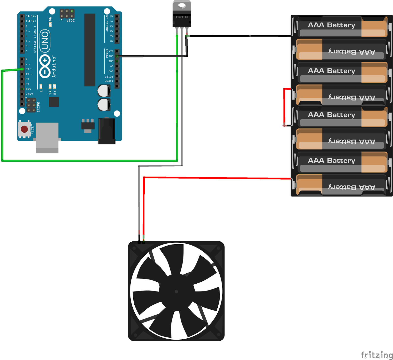
You savaged a fan from an old PC to use it as a ventilator? Just hook it up to 12V and the sucker runs. Well, it runs at a constant speed. Maybe too fast, maybe too noisy. There must be a possibility to slow it down.
The idea
When you apply 12 Volts to it and then remove the power supply, it keeps spinning while getting slower. So if you continuously apply and remove the power, you can control the fan of the speed by the duration of the phases when the 12V is on and when it is not.
What do we need
The Arduino doesn't supply 12 Volts. So we have to use some sort of switch. An electronic switch. A MOSFET. That's a kind of transistor, that can handle the needed current/voltage needed. I used the IRF530N, because it was the only Mosfet I had and it matches the specification of the vent by far ;-). It's a N-channel Mosfet. That means you can control the connectivity of the negative pole of the power source to the fan by applying a positive voltage.
PWM
Pulse Width Modulation is the magic phrase. A digital output pin can only have two possible states. On or off. 1 or 0. HIGH or LOW. While HIGH is typically indicated by an output of 5 Volts (3.3 Volts occasionally) is LOW represented by a 0 Volt output. So how do we simulate an output of 2.5 Volts? Well, simply spoken, if we have a time frame of 10 seconds. Half the time we put out 5 Volts and half the time 0 Volts, we will have an output of 2.5 Volts of the time of those 10 seconds. Wired? Sure. But this is how math works ;-)
Controlling a servo just by the wave of your hand? The wet dream of every Star Wars fan, isn't it? Yeah, mine too! With Microsoft's Kinect or OpenCV and a webcam and a ton of programming you can do it! Or there is a tiny, little module for your Arduino or your Raspberry Pi that can handle some simple gestures. The APDS-9960 can do the job.
It can be set to three different modes. It can work as a proximity sensor. Well, of that we have quite enough in the Arduino world. It can also operate as a ambilight sensor. Not bad. With four of them - each for every corner of your TV - you can make your own low cost ambilight.
But the mode, we're looking for, is the gesture recognition mode. It can detect following hand-movements: - left to right - right to left - up to down - down to up - close to far - far to close
How to use
Well, this is a multi functional sensor. It is developed by SparkFun. Therefore SparkFun published a pretty good library with very useful examples. If you pick the GestureTest example, you can implement easily your own control mechanism.
Video
Connections
Careful
There are some versions of the sensor, marked as APDS-9960, that are really a APDS-9930. That means they are lacking the coolest of all functions - the gesture recognition thing!
Turning a DC motor on and off isn't that much of a problem, is it? But if you want to change direction, you must have a way to switch the polarity that drives your motor. Well, that is what a H-bridge does.
How to control
For each motor, you should have 2 pins to control the output. If you pull one pin HIGH and the other one LOW the motor should spin. If you invert this configuration, the motor will spin in the other direction. Pulling both pins to LOW or both to HIGH will stop the motor.
Now you have the ability to turn the motor on in both directions. If you also want to control the speed of the motors, you should connect it to PWM ports.
Wiring
Video
Pro-Tip
If your motor doesn't spin, you probably have a too low input voltage. These boards are equipped with voltage regulators. So you can try using a higher voltage. I used a 9V battery for the 5V motors myself. Worked perfectly.
For controlling your robot it makes sense to extract the commands for the wheel to spin in separate methods. Make a method for spinning the left wheel in clockwise direction. And one for counterclockwise direction. It's so easier to program some logic to your vehicle.
If you want to add some visual output to your Arduino projects, you'll need a display. If you need only little to display, the LCD 1602 is a quite good solution. But you'll waste about 8 Pins on your Arduino for the display to get working. Luckily there exists a I2C adapter that you can solder right onto the pins of the display. So all you need to connect are the I2C pins, a good library and little of coding.
Wiring
If you already have the I2C adapter soldered onto the board, wiring is quite easy. You should usually have only four pins to hook up. VCC and GND of course. The LCD display works with 5 Volts. So we go for the 5V Pin. The Arduino Uno and Nano can handle the current need for this display. SDA (data line) to analog 4 on your Arduino Uno or Nano. And SCL (clock line) to analog 5 (other Arduinos or ESP might have different pins).
Is yours too small? You want to get more? No, that is no advertisement for a penis enlargement product. It's for a board to extend the numbers of analog inputs to your microcontroller.
It's quite rare that you run out of analog inputs, when using an Arduino Uno, Nano, Micro, etc. Even a ATTiny is already equipped with 4 analog inputs. BUT if you are so keen in using a ESP8266, like I am, you'll find your self in the position having only 1 (!) analog in. This is where a digital to analog converter comes into play.
It's all about libraries
The name of the sensor (ADS1115) already can lead to the conclusion that the board is developed by Adafruit. And of course, if you'll open the library manager in the Arduino IDE and search for ADS1X15. There you have it all. Ready-To-Use library, good commented examples.
I2C on your NodeMcu board
The default pins for I2C on the NodeMcu board are pins D1 (SCL) and D2 (SDA). But the cool thing with the NodeMcu board is, you can define for yourself where the I2C has to be.
With the command: Wire.begin();
You usually start the Wire-library, that is responsible for the I2C bus. But you can also add the pins for SDA and SCL as parameters: Wire.begin(D2, D1);// Wire.begin([SDA-Pin],[SCL-Pin]);
There can be more than one
The ADC1115 has a fixed I2C address, like any other I2C device. Fixed? Not quite! It has up to five different I2C addresses. The default one, and four more addresses, that you can select by connecting the address pin (ADDR) with either SDA, SCL, GND or VDD.
"I like to move it, move it! I like to move it, move it!"
If you want to measure movement, you probably will use one of these sensors. Why you want to measure movement anyway, you ask? Hey, who doesn't want to build a quadcopter? Or a self-balancing robot?
There are 2 common senors, that will do the trick. The GY-61 (ADXL335) and the bigger brother the GY-291 (ADXL345).
The sensors
The GY-61 is the easier sensor to handle. It has VCC and GND and three analog outputs. One for each axis. You can read the sensor values with the analog inputs of an Arduino.
These are quite raw values. And even, when the sensor doesn't seem to move, the values does. So you have to program some method to smooth these values and probably a calibration routine, if you want to use it in a matter of a balanced project.
The GY-291 is a little different. It has an I2C bus. And I recommend to use the library, that is provided by Adafruit. If you're using the Arduino IDE, just search for ADXL345 in the Library Manager.
Video
Which sensor for which project?
Well the advantage of the GY-291 is, that you don't need to interpret the sensor values for yourself. The library does all the work for you. And it has a I2C bus. That means, you won't waste any pins on your controller. Because you can attach several devices to I2C, as long as they have different addresses. The smaller brother, the GY-61, doesn't need much code to operate. The sensor delivers it's values through 3 analog outputs. Well, at least it delivers something. You have to interpret the values for yourself. If you want to build something like a self balancing robot, I would recommend, that you build a small calibration routine.
Both sensors costs about the same.
For one of my next projects, where I want to use an ATtiny. Since the ram of this board is extremely limited and I just want to know, if the sensor is moving anyhow, I'll stick to the GY-61.
This time-of-flight sensor is a laser distance sensor, that emits a 940nm laser. It can measure distance up to 125cm quite accurate. Adafruit delivers a ready-to-use library and a functional example you should try.
Wiring
The sensor is connected via I2C. So you have to use pin 4 and 5 on the Arduino Uno/Nano (other Arduinos may have different pins for I2C). It works with 3.3 volts. But since the breakoutboard has a voltage regulator implemented, you can connect it also to 5 volt.
Video
Casing
=> work in progress
Where to buy?
You can find it on eBay, if you search for "Time of flight"
Or directly from Amazon: Time of flight Arduino Nano